A grounded engineering view of how a custom battery pack, BMS, electronics, charger, testing and customer approval come together.
Introduction
Developing a custom battery pack is not just a matter of connecting a few cells, welding tabs, adding a BMS, closing a box and hoping for the best. In real life, a battery pack is a complete system: chemistry, electrical design, electronics, mechanics, software, thermal behavior, safety, charging, manufacturing, testing, shipping – and, of course, a customer who discovers halfway through the project that a little more current would be nice, less weight would be better, fast charging would not hurt, and all of it still needs to fit into the space that was designed six months ago.
In other words: a good battery pack is not born. It is developed.
Like any serious engineering product, battery-pack development works much better when there is a structured process. Not because engineers are naturally obsessed with Excel files named Final_v7_really_final, but because every early decision affects development time, performance, manufacturability, weight and – let us not forget – cost.
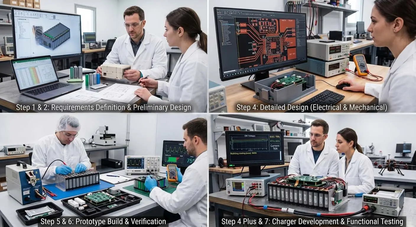
Step 1: Requirements Definition – SRR, before running to select cells
The most important stage in battery-pack development is also the easiest one to underestimate: requirements definition. This is where we ask the questions that are not always pleasant to ask, but are much more painful to ignore later.
When we get down to the basic data, the discussion usually starts with four questions designed to check whether the customer requirements still comply with the laws of physics as currently understood: What operating voltage is really required by the system? What are the continuous, maximum and peak power requirements – and if there are current peaks, for how long? What is the weight limit? What is the volume limit? And, just out of curiosity, what are the odds that a proper Excel file with the real discharge profile already exists?
If there are no weight or volume limitations, life becomes much easier. Most of the complexity and much of the cost come from the demand for a product that is both small and light. Of course, this is a revolving door: as technology improves, customers simply ask for more performance, so the requirement never really disappears.
Then comes the next round: what is the minimum required protection level? Is a mechanical enclosure needed? What connector should be used, and is there already a pinout? Has the required service life been defined? Will the battery be charged inside the system or externally? Who is the end user – a professional, a semi-professional, or the kind of person who somehow manages to force a keyed connector in the wrong direction?
And finally, the environment: operating temperature, storage temperature, vibration, drop, humidity, dust, water, altitude, shipping requirements, standards and safety requirements. We also need to understand whether the pack is for a simple consumer product, an industrial system, a medical device, a defense application, an aviation platform, or simply a system that must not fail at the most inconvenient possible moment.
Good requirements definition is not a wish list. It is a negotiation with physics. Sometimes you cannot have all requirements at once. Sometimes ten more minutes of runtime cost another 500 grams and 25% more product cost. Sometimes a “small” peak-current requirement changes the entire protection concept. And sometimes the most expensive requirement in the system is the one originally marked as nice to have.
Step 2: Preliminary Design – PDR, checking whether it all fits
After requirements definition comes the preliminary design. This is where the technology direction is selected: cell chemistry, number of cells in series and parallel, estimated capacity, operating currents, voltage range, charging method and required protection level.
At this stage we start to understand whether the pack will be a calm and practical LFP design, a high-energy NMC pack, a forgiving and durable LTO pack, or something else entirely. We review available cells, suppliers, lead times, cost, reliability, cycle life, current capability and thermal behavior.
In parallel, the electrical architecture is considered: is a full BMS required, or only a basic PCM? Do we need fuses, cell balancing, communication with the host system, charger identification, current measurement, fault logs or lockout mechanisms?
At this stage we are not yet solving every screw and every copper trace, but we should already know whether the concept is standing on its own feet – or whether it is trying to challenge the law of conservation of energy and win before the end of the quarter.
Step 3: Customer Alignment – before spending development hours
Customer approval is not just a formal checkpoint. It is a critical stage. Here we present the architecture, expected performance, design limitations, assumptions and engineering tradeoffs.
The customer needs to understand what they are expected to receive – and also what they are not receiving. The discussion usually starts with the obvious: operating voltage, capacity, discharge current and runtime. From there it moves to the more specific items: target weight, expected service life, environmental conditions, safety requirements, charging, shipping and compliance.
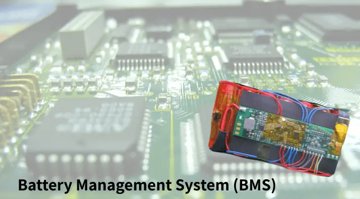
If a BMS is part of the system, this is where its characteristics must also be defined. A BMS has relatively standard functions: cell-voltage measurement, current measurement, temperature monitoring, balancing, protections, SOC calculation, and sometimes communication and fault logging. But for many customers, this is only the starting point. Above the classic BMS come application-specific functions: system identification, charger identification, lockout after fault, temperature-based operating limits, landing detection, accelerometer-based warnings, shock-event logging, fall detection, operation only after a certain condition is met, or communication with a thermal-management system.
In any case, when defining the BMS, the communication type must be addressed early: SMBus, often suitable for small and medium smart batteries; CAN, more common in industrial, defense, vehicle and robotics systems; or UART, RS485 or One-Wire depending on the system. This is not a cosmetic choice. The communication interface affects the circuit, software, test tools, charger, host system and future diagnostics.
It is important to separate the BMS from an application controller inside the pack. Sometimes they sit on the same board. Sometimes the same software handles both. But from a development point of view, these are additional functions. The customer sees “just one more small condition”. The engineer sees a sensor, an algorithm, test cases, edge scenarios, logic, calibration and a new revision of the requirements document.
Step 4: Detailed Design – when the system starts taking shape
Once the direction is approved, detailed design begins. This is where the battery pack stops being a concept and starts becoming a product.
On the electrical side, we design the connection scheme, current protections, voltage distribution, balance wiring, high-current paths, connectors, fuses, measurement points, temperature sensors and communication interfaces. In parallel, the control circuit – usually a BMS or a dedicated management board – is designed not only for the cells, but for the system in which the pack will operate.
PCB layout is performed in coordination with the mechanical design. In battery packs, there is no real separation between “electronics” and “mechanics”. The board must fit where it sits, match the connectors, support the current paths, manage heat, allow assembly, maintain insulation and clearance, withstand vibration and be manufacturable for the 200th unit without hoping the technician is in a generous mood.
And finally, there is what is sometimes mistakenly called “just the enclosure”. The battery enclosure is not only a nice shell. It is part of the environmental, safety and manufacturing concept. It must hold the cells, protect them, possibly remove heat, support assembly, withstand vibration and drop, protect the connectors, and sometimes manage gas or pressure release in case of a fault.
Mechanical design includes materials, insulation methods, retention methods, sealing level, foams, labels, wiring channels and service solutions. In a good pack, nothing “just sits there”. Every part has a reason: to prevent movement, avoid abrasion, spread heat, maintain distance, protect from short circuits, enable assembly or stop the customer from opening something they really should not open.
Step 4 Plus: Charger Development – a parallel product, not a footnote
In parallel with battery-pack development, the charger is often developed as well. It is worth saying clearly: a charger for a custom battery pack is not always an accessory purchased at the end of the project. In many cases, it is a product in its own right, with independent electrical, mechanical, software and safety design.
The charger must match the chemistry, cell count, end-of-charge voltage, charge current, charge profile, temperature limits, safety limits and communication with the BMS if communication exists.
Because chargers are often less constrained by size, weight or shape, there are many good off-the-shelf products available – sometimes even too good. Some chargers allow the charge voltage and current to be adjusted for different batteries. The problem is that many system manufacturers do not want to give the end user the option to “play” with charge parameters, or to provide a universal charger that can be used with every battery the customer owns.
On the other hand, if you need a charger that does not allow the user to make a mistake even if they really try, that is intended for field conditions, or that communicates with the BMS inside the pack, you will likely enter at least a partial development of a dedicated charging system. Such a charger will identify the battery before charging and perform an initial check before the process begins.
Some customers add another layer: they want the charger to serve as a control and diagnostic point for the battery pack. In other words, while the pack is connected to the charger, the charger display shows information from the battery: state of charge, voltage, current, temperatures, cycle count, warnings, active faults, historical faults and sometimes approval or blocking of charge. In this case, the charger becomes not only an energy source, but also the service window of the battery pack.
This approach is very useful when the battery itself is small, sealed, has no display, or is installed in a system without a convenient user interface. In smart products, the battery and charger are not two completely separate products. They are two sides of the same energy system. If one does not understand the other, the user will get a fault – and usually will not care which side is guilty.
A good charger can extend battery life, improve safety, prevent user mistakes and provide important information. A bad charger can do the opposite – quickly, quietly, and usually after the product has already left the factory.
Step 5: Prototype Build – where reality reviews the design
After the design is completed, the first build begins. This is where the prototype or first development batch is assembled. It is the stage where we discover whether the connector is truly accessible, whether a wire is too short, whether one cell hides a screw, whether a label burns near a balancing resistor, and whether the board fits into the enclosure only when held at a 37-degree angle and politely asked to cooperate.
Battery-pack assembly includes cell sorting, voltage and internal-resistance checks, group building, welding or electrical connection, sensor installation, BMS connection, insulation, fixation, continuity tests, insulation tests, polarity checks and basic tests before the first charge.
This stage is critical. The first pack is not only meant to work. It is meant to teach. If you listen carefully, it will tell you where the design is strong, where it is weak, and where someone in the office thought “it will be fine” was an acceptable engineering requirement.
Step 6: Calibration and Safety-Mechanism Verification
Before getting excited about performance, we first check whether the pack knows how to protect itself. Voltage, current and temperature measurements are calibrated and verified. Charge and discharge thresholds are checked, along with overvoltage, undervoltage, overcurrent, short-circuit protection, high- and low-temperature behavior, charge disconnect, discharge disconnect, balancing, communication and fault reporting.
If there is SOC, we verify that it does not only look nice in percentages, but also converges to reality. If there is a fault log, we make sure it records what actually happened, not what would have been pleasant if it had happened. If there is communication with a charger or host system, we check that both sides speak the same language, not just wave a protocol document at each other.
If dedicated sensors exist – accelerometer, pressure sensor, status sensor, landing detection or mechanical-event detection – they also require calibration, testing and edge-case evaluation. A poorly calibrated sensor can make the pack too smart in the wrong place, or too dumb at the wrong moment.
A good safety system is not one that never disconnects. It is one that disconnects at the right time, for the right reason, and returns to operation only when it is truly allowed.
Step 7: Functional Testing – does it actually do the job?
Once the pack is ready, we test whether it does what it was developed to do. We discharge it under real load, measure runtime, continuous current, peak currents, voltage drop, heating, charging, operating cycles, communication with the system and behavior under different use cases.
The charger is tested here as part of the system: charge time, heating, end-of-charge behavior, response to faults, charging at different temperatures, indicators, communication, and what happens when the user disconnects and reconnects it at exactly the worst possible moment.
A good functional test is not only proof that the product works. It is proof that it works under the conditions in which the customer will actually use it, not only under the conditions in which the battery photographs well.
Step 8: Shipping, Documentation and Customer Approval
A Li-Ion battery pack is not shipped like a box of screws. There are shipping requirements, documentation, labeling, state-of-charge limits, packaging, mechanical protections, and sometimes UN38.3 testing or other regulatory requirements depending on the application and destination.
In addition to shipping, proper documentation is required: product specification, charging instructions, user instructions, storage limits, safety warnings, electrical interface, communication protocol if relevant, test results, acceptance report, charger documentation and sometimes maintenance documents or end-of-life instructions.
During customer approval, the pack is checked against the original requirements: performance, dimensions, weight, runtime, safety, charging, communication, integration into the system and behavior under operating conditions. This is the moment when all the small decisions made early in the project arrive for final acceptance.
If the process was done correctly, customer approval is not a surprise. It is a summary. If it was not done correctly, this is the stage where everyone opens the requirements document again and discovers that it was more of a general inspiration than a binding specification.
Conclusion: A battery pack is a product, not a collection of cells
Developing a battery pack from scratch is a multidisciplinary process. It starts with proper requirements definition, continues through cell selection and architecture, and moves through electrical design, BMS design, communication selection, application-specific functions, charger development as a parallel product, PCB layout, mechanical design, assembly, calibration, safety testing, functional testing, documentation, shipping and customer approval.
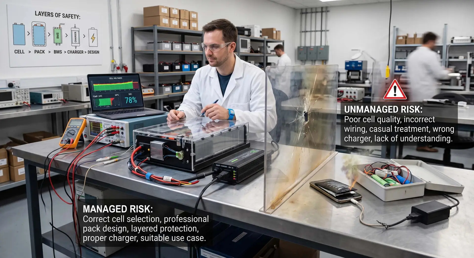
Every stage involves tradeoffs. More energy requires more thermal and safety attention. More current requires conductors, protections and suitable mechanical design. More communication requires software, testing and revisions. More sensors require algorithms and calibration. A smart charger requires full coordination with the battery pack. And if the charger also serves as a diagnostic point, it is no longer just a charger – it is part of the system diagnostics.
In the end, a good battery pack is not the one with the most expensive cell or the smartest BMS. A good battery pack is one designed as a system: suitable for the application, suitable for the required safety level, manufacturable, testable, chargeable, shippable and clear to the customer.
In simple terms: cells can be connected in one day. Developing a battery pack, BMS and charger that work together – that is already a profession.